아래 내용은 도트매트리스와 8개의 저항을 이용하여 16개의 핀을 아두이노와 연결하여

문자를 흐르는 표현을 구성한 것이다.

조금 더 편하게 5개의 핀으로 구성하려면 아래링크의 모듈 추천!!

https://www.icbanq.com/P014162738 


도트 매트릭스를 이용하여 문자가 흐르는 표현 하기

gitgub에서 라이브러리 검색 FrequencyTimer2

FrequencyTimer2 라이브러리는  루키와 paulstoffregen 중

paulstoffregen을 사용

https://github.com/PaulStoffregen/FrequencyTimer2

매트릭스는

공통 애노드 공통 캐소드 형에 따라

스케치 소스 중 일부를 HIGH와 LOW를 변형해야 함.


  • 원형 숫자는 매트릭스 핀번호임.

  • 매트릭스 뒷면 핀 번호 순서

  • 아두이노와 매트릭스 연결

#include <FrequencyTimer2.h>

#define SPACE { \
 {0, 0, 0, 0, 0, 0, 0, 0}, \
 {0, 0, 0, 0, 0, 0, 0, 0}, \
 {0, 0, 0, 0, 0, 0, 0, 0}, \
 {0, 0, 0, 0, 0, 0, 0, 0}, \
 {0, 0, 0, 0, 0, 0, 0, 0}, \
 {0, 0, 0, 0, 0, 0, 0, 0}, \
 {0, 0, 0, 0, 0, 0, 0, 0}, \
 {0, 0, 0, 0, 0, 0, 0, 0} \
 }
 #define H { \
 {0, 1, 0, 0, 0, 0, 1, 0}, \
 {0, 1, 0, 0, 0, 0, 1, 0}, \
 {0, 1, 0, 0, 0, 0, 1, 0}, \
 {0, 1, 1, 1, 1, 1, 1, 0}, \
 {0, 1, 0, 0, 0, 0, 1, 0}, \
 {0, 1, 0, 0, 0, 0, 1, 0}, \
 {0, 1, 0, 0, 0, 0, 1, 0}, \
 {0, 1, 0, 0, 0, 0, 1, 0} \
 }
 #define E { \
 {0, 1, 1, 1, 1, 1, 1, 0}, \
 {0, 1, 0, 0, 0, 0, 0, 0}, \
 {0, 1, 0, 0, 0, 0, 0, 0}, \
 {0, 1, 1, 1, 1, 1, 1, 0}, \
 {0, 1, 0, 0, 0, 0, 0, 0}, \
 {0, 1, 0, 0, 0, 0, 0, 0}, \
 {0, 1, 0, 0, 0, 0, 0, 0}, \
 {0, 1, 1, 1, 1, 1, 1, 0} \
 }
 #define L { \
 {0, 1, 0, 0, 0, 0, 0, 0}, \
 {0, 1, 0, 0, 0, 0, 0, 0}, \
 {0, 1, 0, 0, 0, 0, 0, 0}, \
 {0, 1, 0, 0, 0, 0, 0, 0}, \
 {0, 1, 0, 0, 0, 0, 0, 0}, \
 {0, 1, 0, 0, 0, 0, 0, 0}, \
 {0, 1, 0, 0, 0, 0, 0, 0}, \
 {0, 1, 1, 1, 1, 1, 1, 0} \
 }
 #define O { \
 {0, 0, 0, 1, 1, 0, 0, 0}, \
 {0, 0, 1, 0, 0, 1, 0, 0}, \
 {0, 1, 0, 0, 0, 0, 1, 0}, \
 {0, 1, 0, 0, 0, 0, 1, 0}, \
 {0, 1, 0, 0, 0, 0, 1, 0}, \
 {0, 1, 0, 0, 0, 0, 1, 0}, \
 {0, 0, 1, 0, 0, 1, 0, 0}, \
 {0, 0, 0, 1, 1, 0, 0, 0} \
}


/// 미리 문자를 만들어 놓고


byte col = 0;
 byte leds[8][8];
 
 // pin[xx] on led matrix connected to nn on Arduino (-1 is dummy
 int pins[17]= {-1, 2,3,4,5,6,7,8,9,10,11,12,13,14,15,16,17 };     //  매트릭스의 핀번호 1~16 번까지 연결되는 아두이노 핀을  순서대로 
                                                                   // 맨 앞 -1은 임의용
 // col[xx] of leds = pin yy on led matrix
 int cols[8] = {pins[13], pins[3], pins[4], pins[10], pins[06], pins[11], pins[15], pins[16] };
 
 // row[xx] of leds = pin yy on led matrix
 int rows[8] = {pins[9], pins[14], pins[8], pins[12], pins[1], pins[7], pins[2], pins[5] };

const int numPatterns = 6;        // 글자수를 늘리려면 그수만큼 넘버패턴 수 지정
byte patterns[numPatterns][8][8] = { 
  H,E,L,L,O,SPACE                // 도트메트릭스에 지나갈 문자 넣기
};
 
 int pattern = 0;
 
 void setup() {
   // sets the pins as output
   for (int i = 1; i <= 16; i++) {
     pinMode(pins[i], OUTPUT);
   }
 
   // set up cols and rows
   for (int i = 1; i <= 8; i++) {
     digitalWrite(cols[i - 1], LOW);
   }
 
   for (int i = 1; i <= 8; i++) {
     digitalWrite(rows[i - 1], LOW);
   }
 
   clearLeds();
 
   // Turn off toggling of pin 11
   FrequencyTimer2::disable();
   // Set refresh rate (interrupt timeout period)
   FrequencyTimer2::setPeriod(2000);
   // Set interrupt routine to be called
   FrequencyTimer2::setOnOverflow(display);
 
   setPattern(pattern);
 }
 
 void loop() {
    pattern = ++pattern % numPatterns;
    slidePattern(pattern, 80);       // 80은 속도
}


void clearLeds() {
   // Clear display array
   for (int i = 0; i < 8; i++) {
     for (int j = 0; j < 8; j++) {
       leds[i][j] = 0;
     }
   }
 }
 void setPattern(int pattern) {
   for (int i = 0; i < 8; i++) {
     for (int j = 0; j < 8; j++) {
       leds[i][j] = patterns[pattern][i][j];
     }
   }
 }
 void slidePattern(int pattern, int del) {
   for (int l = 0; l < 8; l++) {
     for (int i = 0; i < 7; i++) {
       for (int j = 0; j < 8; j++) {
         leds[j][i] = leds[j][i+1];
       }
     }
     for (int j = 0; j < 8; j++) {
       leds[j][7] = patterns[pattern][j][0 + l];
     }
     delay(del);
   }
 }
 // Interrupt routine
 void display() {
   digitalWrite(cols[col], HIGH);  // Turn whole previous column off==>다이오드 타입에 따라 LOW(cathode일떄)
   col++;
   if (col == 8) {
     col = 0;
   }
   for (int row = 0; row < 8; row++) {
     if (leds[col][7 - row] == 1) {
       digitalWrite(rows[row], HIGH);  // Turn on this led ==>다이오드 타입에 따라 LOW
     }
     else {
       digitalWrite(rows[row], LOW); // Turn off this led ==>다이오드 타입에 따라 HIGH
     }
   }
   digitalWrite(cols[col],LOW); // Turn whole column on at once (for equal lighting times) ==>다이오드 타입에 따라 HIGH
}

작동 영상

https://youtube.com/shorts/l02p5KTeGF8

#include <Adafruit_NeoPixel.h>
#ifdef __AVR__
#include <avr/power.h>
#endif

#define PIN 6  // 네오픽셀 연결핀
#define NUMPIXELS 24  // 네오픽셀 수
 
 Adafruit_NeoPixel pixels = Adafruit_NeoPixel(NUMPIXELS, PIN, NEO_GRB + NEO_KHZ800);
 // 네오픽셀을 pixels로 정의
int delayval = 500; // delay for half a second
int a;
 
void setup() {
  #if defined (__AVR_ATtiny85__)
    if (F_CPU == 16000000) clock_prescale_set(clock_div_1);
  #endif
  pixels.setBrightness(20); // 0~255 사이의 값으로 최대 밝기 조절 (255가 최대)
  pixels.begin(); // This initializes the NeoPixel library.
  pixels.show();
 }
 
void loop() {
  a = analogRead(A0);       
  a = constrain(a,100,1000);
  a = map(a, 100,1000,0,23);      // A0핀에서 받은 값을 100~1000로 제한후, 0~23 값으로 변환
  PixeOFF(a);                     // 함수  a번째 픽셀을 제외한 나머지 부분 픽셀 끄기 함수 호출
  pixels.setPixelColor(a, pixels.Color(0,150,0));     // a번째 픽셀 켜기
                                                  // 또는 pixels.setPixelColor(a, 0xff33cc);   로 직접 색생표를 넣어도됨.
  pixels.show();
 }
 
void PixeOFF(int num){          // 만약 5번째만 키려면 0~3, 5~23 번은 꺼야한다.
  for(int i = 0; i < num ; i++){
    pixels.setPixelColor(i, pixels.Color(0,0,0));     // 0~(i-1) 번째 칼라를 0x000000 값으로 
    pixels.show();
  }
  for(int i=24;i>num;i--){
    pixels.setPixelColor(i, 0);                         // (i+1)~23 번째 칼라를 0 값으로 
    pixels.show(); 
  }
}


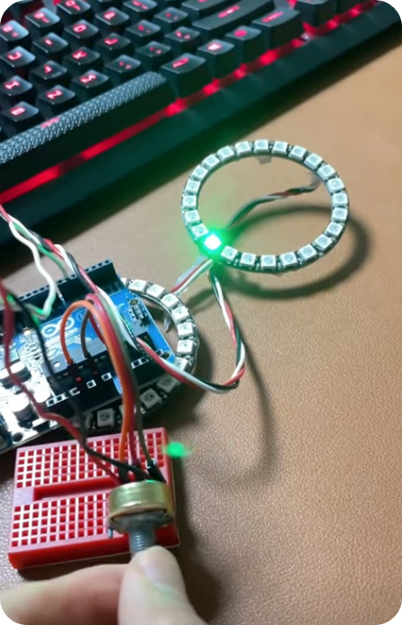
포텐셜미터로 네오픽셀링 이동 작동영상

https://youtube.com/shorts/VZgRO1T2vjs

'아두이노_프로세싱 > 아두이노' 카테고리의 다른 글

도트 매트릭스 문자 흐름  (0) 2023.10.02
LCD쉴드 + 가속도센서 각도 측정  (0) 2013.06.28
가속도 센서로 각도 측정  (1) 2013.06.28
가속도센서  (1) 2013.06.26
LCD 쉴드 자작  (0) 2013.04.25

가속도 센서로 각도를 측정하여

자작한 LCD쉴드에 출력


serial모니터로 출력하여 측정된값을

컴퓨터로 출력하여 확인하지 않고

아두이노에 LCD를 부착하여 측정값을 바로

확인할수 있도록 하였다.


LCD쉴드 http://eskelt.tistory.com/78  글 참고

가속도센서 http://eskelt.tistory.com/79 글 참고

가속도센서로 각도측정 http://eskelt.tistory.com/80 글 참고


소스 스케치

============================================================================

#include <LiquidCrystal.h>

LiquidCrystal lcd(12, 11, 5, 4, 3, 2);
float x,y,z;

void setup(){
  lcd.begin(16, 2);
}

void loop(){
 
  x = analogRead(0);
  y = analogRead(1);
  z = analogRead(2);
 
  float xsintheta = constrain(mapinfloat(x,268,406,-1,1),-1,1);
  float ysintheta = constrain(mapinfloat(y,267,406,-1,1),-1,1);
  float zsintheta = constrain(mapinfloat(z,275,412,-1,1),-1,1);


  float xtheta = asin(xsintheta)*180/PI;
  float ytheta = asin(ysintheta)*180/PI;
  float ztheta = asin(zsintheta)*180/PI;
 
  lcd.clear();
  lcd.setCursor(0,0);
  lcd.print("x: ");
  lcd.setCursor(5,0);
  lcd.print(xtheta);
 
  lcd.setCursor(0,1);
  lcd.print("y: ");
  lcd.setCursor(5,1);
  lcd.print(ytheta);
 
  delay(100); 
}

float mapinfloat(float i, float imin,float imax, float omin, float omax){
  float o = (i-imin)*(omax-omin)/(imax-imin) + omin;
  return o;
}

============================================================================


작동 영상

영상에서는 x축만 출력하였다.

참고로 -70~70도 사이에서는 비교적 정확하게 측정되나

-70과 70도를 벗어나면서 정확한 값을 측정하기 어려움.


+ Recent posts